


We have been manufacturing high-quality printed circuit boards for over 30 years. Thanks to our accumulated experience, continuous investment and optimization of our machinery and our highly qualified staff, we are able to guarantee the best possible quality of our products due to the high degree of automation.
Compliance with industry-standard tolerances and production in accordance with the applicable IPC guidelines and standards are basic requirements for us.
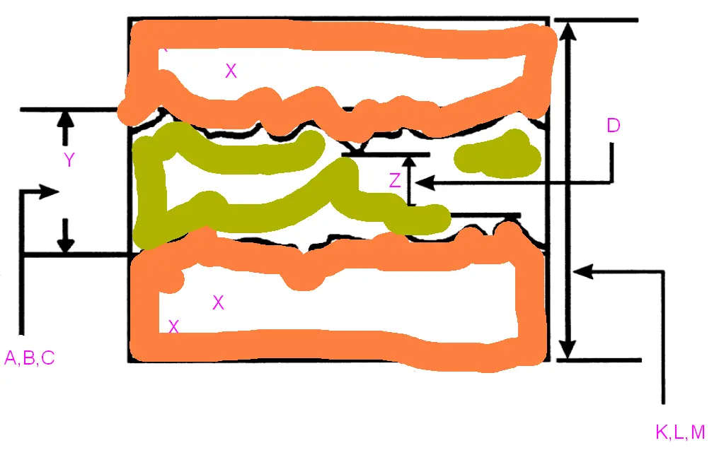
We produce in accordance with the current version of IPC-A-600, Class 2 and, on request, Class 3.
These specifications and tolerances are not set in stone. However, you should discuss any deviating or restricted specifications with our team in advance. The following values and tolerances apply as standard specifications:
- General tolerances
- Additional prints
- Surfaces
| General | Value/tolerance |
|---|---|
| Material thickness | ±10% |
| Final diameter PTH | ±75μm |
| Final diameter NPTH | ±50μm |
| Galvanic copper plating | min. 20μm |
| Minimum hole mechanically drilled | 0,15mm |
| Microvia mechanically or laser drilled | 0,10mm |
| Min. Restring | 0,05mm |
| Aspect ratio standard holes | 8:1 (max. 13:1) |
| Aspect Ratio Blindvias | 1:1 |
| Positional accuracy of the drill holes | ±0,05mm |
| Positioning accuracy contour | ±0,15mm |
| Trackwidth | ±0,05mm or ±20% |
| Add. printing | Value/tolerance |
|---|---|
| Thickness of the solder mask | min. 12µm |
| Structure width for solder resist | min. 50µm |
| Position accuracy solder mask | ±0,10mm |
| Structure size legendprint | min. 150um (is clipped on copper pads) |
| Position accuracy legendprint | ±0,10mm |
| Structure width for peelable | min. area Ø2mm |
| Positioning accuracy peelable | ±0,20mm |
| Surfaces | Value/tolerance |
|---|---|
| HAL SnPb (lead tin, leaded, not RoHS-compliant) | Thickness 2-50um, ca.63% Sn + 37% Pb |
| HAL leadfree | Thickness 2-50um, ca. 99,9% Sn + 0,1% Pb |
| Chem. Ni/Au (ENIG) | 4-7μm Ni + min. 0,01μm Au |
| Chem. Ni/Pd/Au (ENEPIG) | 4-7μm Ni + 0,2 μm Pd + min. 0,01μm Au |
| Chem. Sn (Tin) | min. 0,7μm Sn |
| Chem. Ag (Silver) | min. 0,07μm Ag |
| Edgeconnector (galv. hardgold) | 4-7μm Ni + min. 0,8μm Au |
In the following, we supplement this list with generally applicable
Tolerance tables for base materials and general tolerances according to DIN 7168 (Part 1)
Tolerances of base material
Permissible thicknesses of copper-clad base materials
| Thickness and tolerances for laminates according to IPC-4101 | ||||||||
|---|---|---|---|---|---|---|---|---|
| Nominal thickness | Class A/K | Class B/L | Class C/M | Class D | ||||
| 0,025 bis 0,119 | ±0,025 | ±0,018 | ±0,013 | +0,025/-0,013 | ||||
| 0,120 bis 0,164 | ±0,038 | ±0,0025 | ±0,018 | +0,030/-0,018 | ||||
| 0,165 bis 0,299 | ±0,050 | ±0,038 | ±0,025 | +0,038/-0,050 | ||||
| 0,300 bis 0,499 | ±0,064 | ±0,050 | ±0,038 | +0,050/-0,038 | ||||
| 0,500 bis 0,785 | ±0,075 | ±0,064 | ±0,050 | +0,064/-0,050 | ||||
| 0,786 bis 1,039 | ±0,165 | ±0,100 | ±0,075 | n/a | ||||
| 1,040 bis 1,674 | ±0,190 | ±0,130 | ±0,075 | n/a | ||||
| 1,675 bis 2,564 | ±0,230 | ±0,180 | ±0,100 | n/a | ||||
| 2,565 bis 3,579 | ±0,300 | ±0,230 | ±0,130 | n/a | ||||
| 3,580 bis 6,350 | ±0,560 | ±0,300 | ±0,150 | n/a | ||||
All dimensions in mm.
Class A, B, C are used for measuring the dielectric without copper. Class K, L, M include copper when measured. Class D is typically used for very thin materials after the etching process.
Class B/L is the standard for PCBauch: gedruckte Schaltung, engl.: PCB – Printed circuit boar… More production. Above 0.8 mm thickness class L applies, below class B.
| Glass fiber CEM-3, FR-4 | ||||||||
|---|---|---|---|---|---|---|---|---|
| DIN EN 60249 | NEMA LI-1 | MIL-S-13949 | ||||||
| Nominal thickness | Normal | Tight | Class 1 | Class 2 | Class 1 | Class 2 | Class 3 | Class 5 |
| 0,5 | - | ±0,07 | - | - | ±0,06 | ±0,05 | ±0,04 | -0,04 | +0,05 |
| 0,8 | ±0,15 | ±0,09 | ±0,17 | ±0,10 | ±0,17 | ±0,10 | ±0,08 | -0,08 | +0,09 |
| 1,0 | ±0,17 | ±0,11 | - | - | ±0,17 | ±0,10 | ±0,08 | -0,08 | +0,09 |
| 1,2 | ±0,18 | ±0,12 | ±0,19 | ±0,13 | ±0,19 | ±0,13 | ±0,08 | -0,08 | +0,09 |
| 1,5 | ±0,20 | ±0,14 | ±0,19 | ±0,13 | ±0,19 | ±0,13 | ±0,08 | -0,08 | +0,09 |
| 2,0 | ±0,23 | ±0,15 | - | - | ±0,23 | ±0,18 | ±0,10 | -0,10 | +0,11 |
| 2,4 | ±0,25 | ±0,18 | ±0,23 | ±0,18 | ±0,23 | ±0,18 | ±0,10 | -0,10 | +0,11 |
| 3,2 | ±0,30 | ±0,20 | ±0,31 | ±0,23 | ±0,31 | ±0,23 | ±0,13 | -0,13 | +0,14 |
All dimensions in mm.
| Hard paper FR-2, FR-3, CEM-1 | ||||||||
|---|---|---|---|---|---|---|---|---|
| DIN EN 60249 | NEMA LI-1 | MIL-S-13949 | ||||||
| Nominal thickness | Normal | Tight | Class 1 | Class 2 | Class 1 | Class 2 | Class 3 | Class 5 |
| 0,8 | ±0,09 | - | ±0,11 | ±0,08 | - | - | - | - |
| 1,0 | ±0,11 | - | - | - | - | - | - | - |
| 1,2 | ±0,12 | - | ±0,14 | ±0,09 | - | - | - | - |
| 1,5 | ±0,14 | - | ±0,15 | ±0,10 | - | - | - | - |
| 2,0 | ±0,15 | - | - | - | - | - | - | - |
| 2,4 | ±0,18 | - | ±0,18 | ±0,13 | - | - | - | - |
| 3,2 | ±0,20 | - | ±0,23 | ±0,15 | - | - | - | - |
All dimensions in mm.
General tolerances according to DIN 7168 (Part 1)
Length dimensions
Upper and lower dimensions for length measurements
except for rounding radii and chamfer heights (bevels)
| Degree of accuracy |
>0,5 ≤3 |
>3 ≤6 |
>6 ≤30 |
>30 ≤120 |
>120 ≤400 |
>400 ≤1000 |
>1000 ≤2000 |
|---|---|---|---|---|---|---|---|
| F (fine) | ±0,05 | ±0,05 | ±0,1 | ±0,15 | ±0,2 | ±0,3 | ±0,5 |
| M (medium) | ±0,1 | ±0,1 | ±0,2 | ±0,3 | ±0,5 | ±0,8 | ±1,2 |
| G (rough) | ±0,15 | ±0,2 | ±0,5 | ±0,8 | ±1,2 | ±2,0 | ±3,0 |
| SG (very rough) | - | ±0,5 | ±1,0 | ±1,5 | ±2,0 | ±3,0 | ±4,0 |
All dimensions in mm.
For nominal dimensions below 0.5 mm, the values must be entered directly at the nominal dimension
Rounding radii and chamfer heights
Upper and lower dimensions for
Rounding radius and chamfer heights (bevels)
| Degree of accuracy |
>0,5 ≤3 |
>3 ≤6 |
>6 ≤30 |
>30 ≤120 |
>120 ≤400 |
|---|---|---|---|---|---|
| F (fine) | ±0,20 | ±0,50 | ±1,0 | ±2,0 | ±4,0 |
| M (medium) | ±0,20 | ±0,50 | ±1,0 | ±2,0 | ±4,0 |
| G (rough) | ±0,2 | ±1,0 | ±2,0 | ±4,0 | ±8,0 |
| SG (very rough) | ±0,2 | ±1,0 | ±2,0 | ±4,0 | ±8,0 |
All dimensions in mm.
For nominal dimensions below 0.5 mm, the values must be entered directly at the nominal dimension
Angular dimensions
Upper and lower dimensions for
Angular dimensions
| Degree of accuracy | ≤10 |
>10 ≤50 |
>50 ≤120 |
>120 ≤400 |
>400 |
|---|---|---|---|---|---|
| F (fine) | ±1° | ±30' | ±20' | ±10' | ±6' |
| M (medium) | ±1° | ±30' | ±20' | ±10' | ±6' |
| G (rough) | ±1°30' | ±50' | ±25' | ±15' | ±10' |
| SG (very rough) | ±3° | ±2° | ±1° | ±30' | ±20' |
All dimensions in angular units for nominal dimension range of the shorter leg
in degrees( ° ) and minutes( ‘ ).